
ProfiNet
L'opzione bus di campo ProfiNet è certificata dal consorzio ufficiale PROFIBUS Nutzerorganisation e.V. ed è sviluppata nella versione RT (Real Time) e nella versione IRT (Real Time Isochronous) per classi di applicazione come AC1 - AC3 - AC4. Tutti gli azionamenti HDT dotati di questo bus di campo offrono le stesse funzionalità.
HDT - Specifiche tecniche del protocollo ProfiDrive implementate:
Classi di applicazione (AC):
- AC1 - Azionamento standard - Velocità, coppia, controllo corrente
- AC3 - Posizionatore eseguito all'interno dell'azionamento secondo le specifiche AC3 adatte per PLC Siemens serie 1200 (Modalità programma, Modalità inserimento manuale)
- AC4 - I profili e le funzioni vengono generati all'interno del PLC mediante oggetti tecnologici e l'azionamento chiude l'anello di velocità e acquisisce la sua posizione- Asse elettrico (non standard - specifiche HDT)
- Controllo della pressione (non standard - specifiche HDT)
Informazioni Tecniche su ProfiNet
ProfiNet (abbreviazione di Process Field Net) è un bus di campo "aperto e in tempo reale" basato sulla tecnologia Ethernet standard e conforme a IEEE802.3. adatto per la gestione dei dati industriali.ProfiNet utilizza il cosiddetto protocollo PROFIdrive per gestire l'accesso ai dati del servoazionamento, che definisce un'intera serie di parametri e dati standard.ProfiNet è sviluppato su 3 profili, distinti per campo di utilizzo, prestazioni e complessità. Il protocollo ProfiDrive è distribuito su 5 classi di applicazioni (CA).
ProfiNet - Profili
- ProfiNet TCP / IP (No Real-time), profilo non deterministico per applicazioni in cui il tempismo non è critico che utilizza i protocolli TCP / IP e UDP / IP standard utilizzati per parametrizzazioni, configurazioni e operazioni di lettura / scrittura acicliche con cui i tempi di ciclo > 100 ms sono raggiunti.
- ProfiNet RT (Real-Time), profilo deterministico utilizzato per il trasferimento di dati e allarmi ciclici standard. I dati trasferiti tramite RT bypassano l'interfaccia TCP / IP per accelerare lo scambio di dati con il PLC consentendo di creare applicazioni con tempi di ciclo <10 ms. Consente l'utilizzo di alcune funzioni "oggetti tecnologici" del PLC. Questo profilo è paragonabile in termini di funzionalità al ProfiBus DP V0.
- ProfiNet IRT (Isochronous Real Time), profilo deterministico ad alta velocità utilizzato per le applicazioni Motion Control e che richiede, come per EtherCat, una Ethernet modificata con un ASIC personalizzato. Sfruttare appieno gli "oggetti tecnologici" messi a disposizione dei PLC Siemens. Questo profilo consente tempi di ciclo inferiori a 1 ms.
ProfiDrive - the "Application Class"
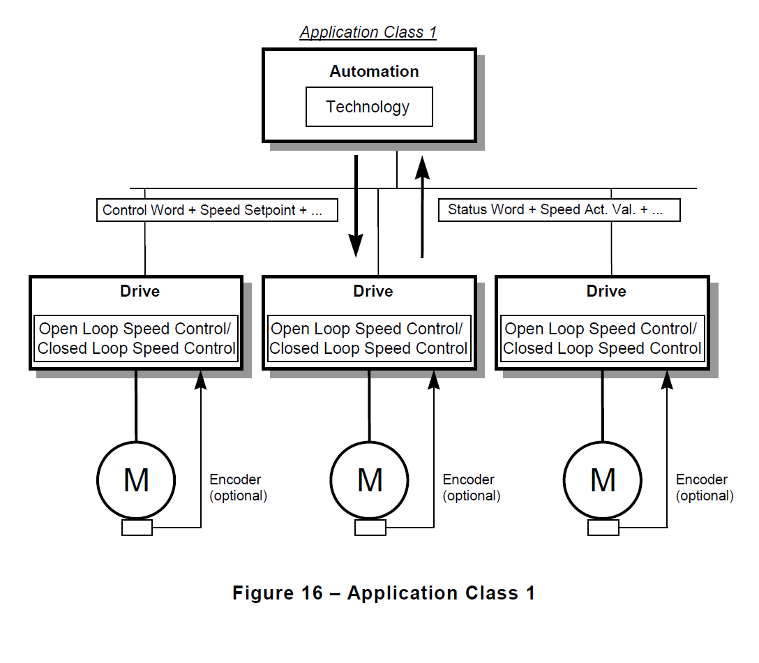
AC1 - Standard Drive - speed, torque and current setpoint interface.
In the simplest case, the drive is controlled via a primary setpoint (for example, speed setpoint)(see Figure 16). The speed control is governed completely in the drive controller. The PLCincludes all technological functions for the automation process. The field bus is merely thetransmission medium between the automation system and the drive controller. The Cyclic DataExchange communication service is used. This type of application is used primarily in the field ofclassical drive engineering (for example, conveyor systems). A PLC is usually used as theautomation system. Clock Synchronous Operation may be used, but is typically not necessary forthis Application Class.
AC2 - Standard Drive with distributed technology controller.
Application Class 2 (has not been developped by HDT) is dedicated to implementing drive applications (seeFigure 17). In this version, the automation process is broken down into many small subprocesses.The technology functions are no longer exclusively in the central PLC, but are also distributed inthe drives. The communication interface serves as the technology interface. The data that isexchanged via the bus system between the individual automation components and drivecontrollers may be individually defined. This variant assumes, however, that communication isguaranteed in all directions; that is, DO IO Data transfer should be possible also between DriveObjects (Axis). To realise applications like setpoint cascades, winders, and speed synchronism Clock Synchronous Operation should be possible. The technology functions are realised in the drive.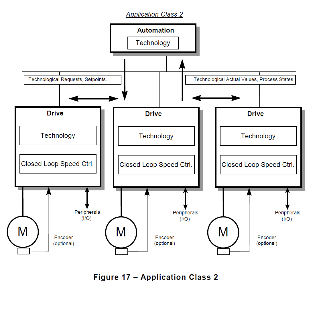
AC3 - Single Axis positioning drive with local Motion Control
In Application Class 3 (see Figure 18), only the technology functions for the automation processare still in the PLC. Positioning requests are stored in the Drive. A single positioning request isstarted via a command from the Controller (e.g. PLC). Interpolation and position control as wellas speed control are implemented directly in the drive. Since in this variant, all time-criticalcontrol algorithms are hidden in the drive controller, Clock Synchronous Operation is onlynecessary if complex tracking for multiple axes shall be coordinated.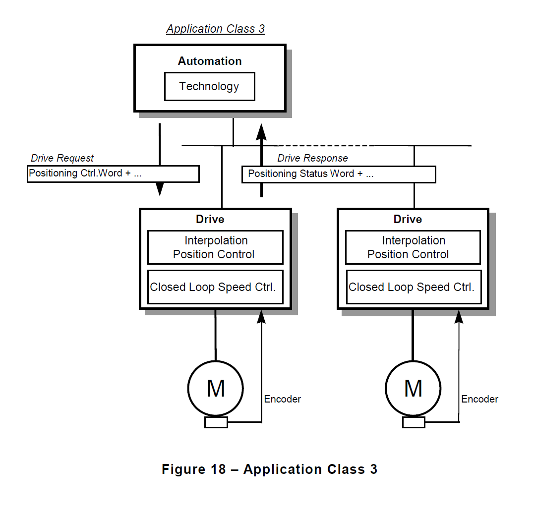
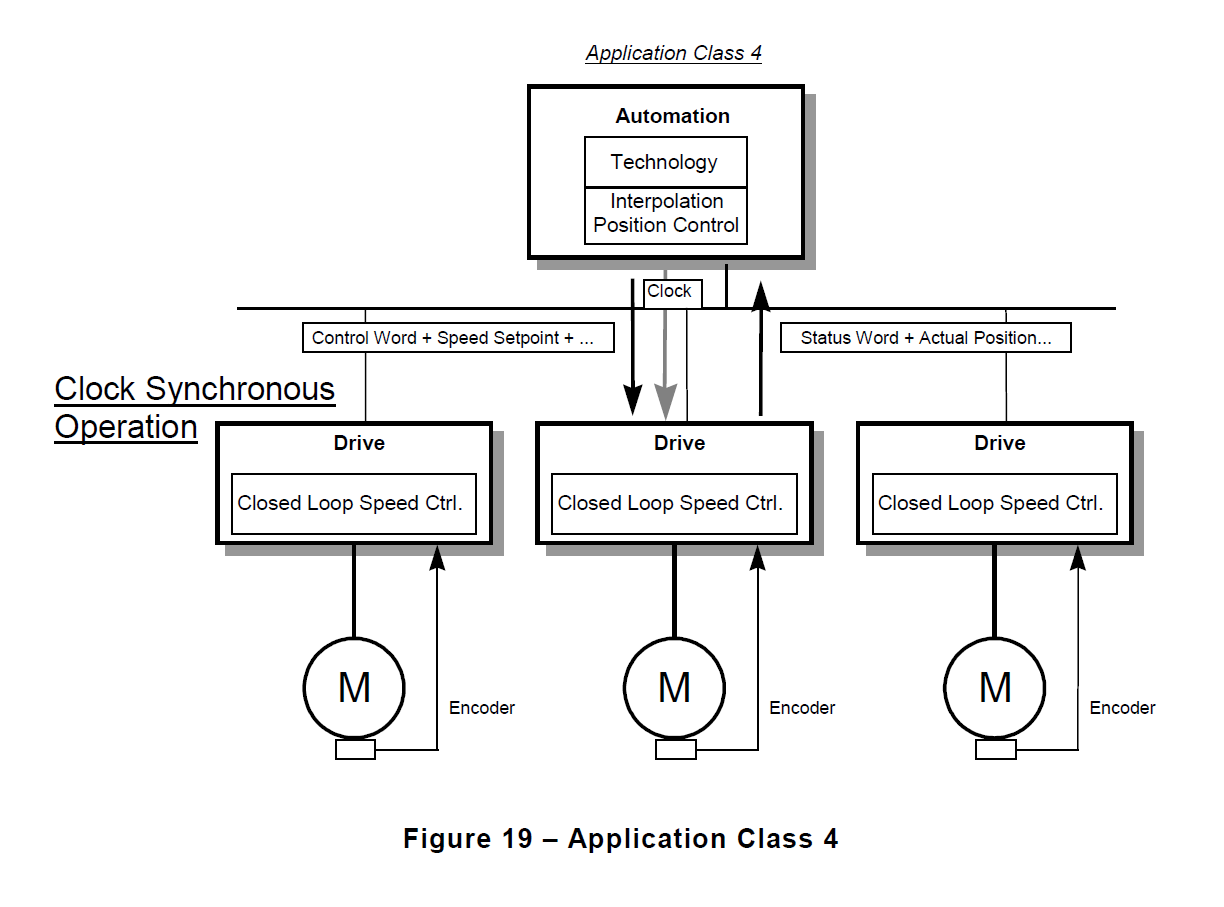
AC4 - Motion Control with central interpolation and speed setpoint interface
Application Class 4 (see Figure 19) shows the position closed loop control closed via thecommunication system. Drives for manipulator and robotic applications often require acoordinated motion sequence of several drive systems. Motion control is primarily implementedvia a central automation unit (NC). For each drive, these controllers calculate special setpointprofiles. By coordinating several drives (for example, for the XYZ axis), certain trajectories maybe implemented. In addition to the required technology functions for the automation process, theautomation system also includes the functions for interpolation and position control of the drive.Speed setpoint values and actual values as well as the position actual value are transferred viaCyclic Data Exchange. The drive controller essentially only includes the algorithms for closedloop speed control and actual position acquisition. Since the position is controlled via the bussystem, Clock Synchronous Operation is necessary and shall be very precise. Additionally, the DSC-functionality may be used to increase the rigidity and dynamic response of the control loop.